|
|
Post by justin on Jun 10, 2019 2:03:56 GMT
 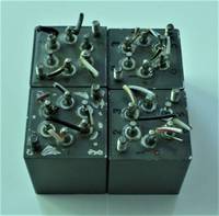 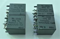 Hello everyone, I'm very happy to have found this resource. I recently purchased 4 Transonics transformers from the early 1960's for very cheap. They are 1000/600/600ohm. I want to build a 2 channel xlr box for these transformers, hopefully to put 2 in series on each channel--if that's somewhat reasonable. I have a couple of questions about that. I have included pics of the transformers on here below. My questions are: 1) How do I wire xlr to them in, and out? 2) If I'm wiring 2 in series, how do I do that, and, should the first one be wired--if this is even possible--so that it outputs 1000ohm into the 600ohm input of the next? 3) Can 4 transformers be wired up to go in a small aluminum housing? I want to use a heavy aluminum box to plug my xlr flanges into. Thanks for any advice anyone can give. I am new at this and I am excited that this is my first build experiment. -Justin </attachment></attachment></attachment> |
|
|
|
Post by Michael Lawrence on Jun 10, 2019 10:42:24 GMT
Hi Justin -
It seems like you are missing a few puzzle pieces here. Transformers are described as a turns ratio, not impedance measurements. A transformer has no inherent impedance (an input xfmr will have a non-negligible DC resistance but that's something else). Rather, it will literally "transform" the impedance of the input load as seen by downstream devices, by turns ratio squared. So the impedance measured at the output of a transformer depends on what is connected to the input terminals.
Connecting a load to the 600Z pair of terminals on each side is simply a 1:1 isolation transformer which will give galvanic isolation, and change neither the voltage nor the impedance of the signal source as seen by the load. 1000:600 is a voltage step down of two thirds (.6V out for 1V in) and a Z ratio of two thirds squared, or 0.3, so a standard 200Z mic would look like 60 ohm to the line.
Modern audio devices should be interconnected using impedance bridging, not impedance matching. The 600 ohm dog is dead. It is a holdover from telephone and tube interconnect and will cause large signal loss with modern devices.
So I guess I am not clear on what your desired outcome is with this project.
In any case I would advise using plastic XLR housings to isolate them from the chassis.
|
|
|
|
Post by justin on Jun 10, 2019 13:06:22 GMT
Hi Michael,
Thank you for that information. I want to wire these in series to use on my mix buss. From what I have read of my current gear, the output into the transonics would be less than 200 ohm.
Does this avert the mismatch with modern gear that you speak of?
|
|
|
|
Post by rock on Jun 11, 2019 3:43:12 GMT
I'm really just trying to understand exactly what you are trying to achieve by connecting 4 transformers in series to your mix buss. Are you connecting some external input device to your mix buss? Are you combining your mix buss to output an external device? If so, there are other ways to do these things. In the meantime, you're melting my brain (which is already pretty soft, Ha Ha)
|
|
|
|
Post by rock on Jun 11, 2019 3:56:16 GMT
Not knowing what you are even doing, I do have some advice in general for experimenting: Don't worry about enclosures and connectors in the beginning, save that for the fabrication stage. Start with alligator clip jumpers to connect up your concoction and see if it works the way you expect. If it doesn't work, get out your DVM, signal generator and scope and reconnect stuff until it works the way you want it to. If that doesn't work, draw up a schematic and work out you design on paper then check it with any electronics theory and math you may know... Or, do it the other way around.
|
|
|
|
Post by justin on Jun 11, 2019 12:16:56 GMT
Thanks, Rock, you make some points that I needed to know. What I want to do is simply add these transformers in a 2 channel config, with 2 in series on each side. I want to put them after my DAW, my interface, and an SSL Fusion (the latter which I read has an output impedance of less than 200 ohm). In reading about transformers being used like this, some people have written that they can be dangerous to modern IC based gear, because they can overload the amp. One person said that sometime low frequencies in the transformers can lead to a "dead short" which could be extremely bad for IC based kit. I don't know if any of that is true, and it did seem as if people are using a variety of transformers in this application, including some output transformers.
I have read that as long as the input impedance of the transformers is more than the output of the SSL FUSION then I'll be okay, but I don't know if that's true.
The transformers I have purchased were supposedly used in a DI for a radio station. That's all I know about them. Googling that company Transonic, turns up very little, and it appears they went out of business in the early 1960's.
I think your alligator clip idea makes the most sense to start testing. My remaining problems are: I am not sure how to wire these in series and keep them 1:1 ratio, and, I am not sure of any risk to my IC equipment, like a "dead short" etc.
|
|
|
|
Post by rock on Jun 11, 2019 22:04:58 GMT
Hi Justin, you did clear up what you want to do but you did not mention WHY. Is it that you believe these transformers will enhance your sound? If you want to add something to your sound, check out Ethan's project the-audio-expert.freeforums.net/thread/536/mojo-maestro-transformer You can read how the transformer can offer soft clipping if it's driven into saturation. |
|
|
|
Post by justin on Jun 12, 2019 1:15:07 GMT
Thanks, Rock. I will try to track down that article. Just reading the comments that come up on your link, it seems that I probably could stick with the build I am already hoping for, since I have transformers that are very old, and will probably sound like transformers. I am still not sure how to wire the ones I have, but it's true that more knowledge is a good, even when it doesn't answer my questions.
|
|
|
|
Post by rock on Jun 12, 2019 13:13:57 GMT
|
|
|
|
Post by justin on Jun 12, 2019 13:47:17 GMT
Many thanks. I will read up first before attempting to follow your suggestions. Thanks again
|
|
|
|
Post by justin on Jun 13, 2019 20:43:28 GMT
Hi Rock,
I am getting closer to understanding this, though slowly. I will soon begin to experiment with alligator leads. For wiring in series of these two xfrmers, if done correctly, this would not draw too much current? Or, is wiring these two xformers in series a risk of overloading the interface amp?
|
|
|
|
Post by rock on Jun 13, 2019 23:50:22 GMT
Again my suggestion is to wire ONE (1) and get it to work. If that works OK then just wire the second one in just like the first. If that works and you really want two in series, we can talk about polarity before you make your final build. If you study enough, may be you can answer the polarity question for yourself! I'm not going into it now because it's detail we don't need right now. Just get one working first.
|
|
|
|
Post by justin on Jun 14, 2019 0:27:03 GMT
ok, that makes sense.
|
|


