

Post by Ethan Winer on Dec 10, 2016 22:35:38 GMT
I mentioned in the Acoustics section that I've been very busy for the past few months, and will continue to be busy for a few more months. Probably through the end of January. One project is working on an update to my Audio Expert book, and the other is designing a complex electronic device to test audio gear. This started as a way to prove that the $3 RCA wire that comes free with your CD player passes audio exactly as well as an RCA wire that sells for $1,000. The key is the null test, which verifies the sameness (or not) of two signals by subtracting one from the other to see what remains. I explain how nulling works, and why it's an incredibly valuable test method, in my AES Audio Myths video. This link starts at that section:
When I started this project I figured it would cost about $300 for parts, and take a month or two to design and build a prototype. Then if it worked well enough I'd try to sell some for a few hundred dollars each. Well, that was back in July and now, five months and $1,700 later, I'm coming into the home stretch. This tester has evolved into a serious device that I hope will be as sensitive as the dedicated testers that cost $10,000 to $20,000. One important key to value is how quiet a signal can be measured. I hope to be able to "see" down to -110 dB if not lower. The prototype is designed to get down to -120 dB but we'll see if that's actually possible. As you might imagine, the circuit design, component selection, and PC board layout are all critical to minimizing noise and hum!
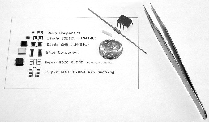
I haven't designed circuits for many years, and everything has changed since then! You can't even buy the latest high performance op-amps and other ICs in the old DIP style - everything now is surface mounted (SMD) which makes assembly more difficult. But I have several expert friends who have helped me with both the circuits and assembly advice. One even loaned me a $400 soldering station meant for tiny parts. I did some trial soldering using parts I bought and scrap PC boards she loaned me, and it went well enough considering I'm an old coot with old eyes. The photo below shows an assortment of SMD parts, next to a normal size 8-pin IC and 1/4 watt resistor. The dime and grain of rice give another sense of scale. The 0805 and 2416 size numbers specify the length and width, in this case 0.08 by 0.05 inches for the smallest part shown. Parts much smaller than these are available for assembly by machine (only)!
Anyway, the circuits are all designed, and so are the 4-layer PC board and front panel. I still have to send the PC board out to be manufactured, and I'm waiting on two key parts that won't be in stock until January. All told, the Null Tester contains 50 op-amps, 5 power supply regulators, 6 PhotoFETs (optical isolators to allow digitally controlling more than 100 dB of gain), 4 timer ICs, 4 digital gate ICs, 1 power amplifier chip, 6 transistors, 7 pots, 12 switches, and 22 input and output jacks. Whew! Here's an overview of the PC board:
And this is a mock-up of the front panel:
As I mentioned the front panel is done, and all the controls and jacks are mounted though not yet wired. But I haven't gotten around to taking a photograph of the panel yet so this will have to do for now.
When I started this project I figured it would cost about $300 for parts, and take a month or two to design and build a prototype. Then if it worked well enough I'd try to sell some for a few hundred dollars each. Well, that was back in July and now, five months and $1,700 later, I'm coming into the home stretch. This tester has evolved into a serious device that I hope will be as sensitive as the dedicated testers that cost $10,000 to $20,000. One important key to value is how quiet a signal can be measured. I hope to be able to "see" down to -110 dB if not lower. The prototype is designed to get down to -120 dB but we'll see if that's actually possible. As you might imagine, the circuit design, component selection, and PC board layout are all critical to minimizing noise and hum!
I haven't designed circuits for many years, and everything has changed since then! You can't even buy the latest high performance op-amps and other ICs in the old DIP style - everything now is surface mounted (SMD) which makes assembly more difficult. But I have several expert friends who have helped me with both the circuits and assembly advice. One even loaned me a $400 soldering station meant for tiny parts. I did some trial soldering using parts I bought and scrap PC boards she loaned me, and it went well enough considering I'm an old coot with old eyes. The photo below shows an assortment of SMD parts, next to a normal size 8-pin IC and 1/4 watt resistor. The dime and grain of rice give another sense of scale. The 0805 and 2416 size numbers specify the length and width, in this case 0.08 by 0.05 inches for the smallest part shown. Parts much smaller than these are available for assembly by machine (only)!
Anyway, the circuits are all designed, and so are the 4-layer PC board and front panel. I still have to send the PC board out to be manufactured, and I'm waiting on two key parts that won't be in stock until January. All told, the Null Tester contains 50 op-amps, 5 power supply regulators, 6 PhotoFETs (optical isolators to allow digitally controlling more than 100 dB of gain), 4 timer ICs, 4 digital gate ICs, 1 power amplifier chip, 6 transistors, 7 pots, 12 switches, and 22 input and output jacks. Whew! Here's an overview of the PC board:
And this is a mock-up of the front panel:
As I mentioned the front panel is done, and all the controls and jacks are mounted though not yet wired. But I haven't gotten around to taking a photograph of the panel yet so this will have to do for now.


